Create Vivado Hardware Design for Zedboard
In this tutorial, we will create the hardware design for the Zedboard to be used as a Vitis acceleration platform. This tutorial is adapted from Xilinx Vitis Tutorial.
Create Vivado project
- Launch Vivado
- Create a Vivado project named zed_custom_platform.
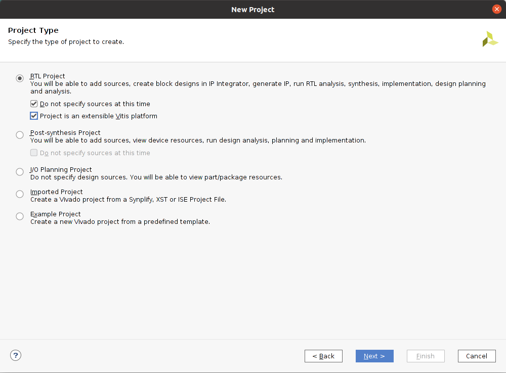
- Select File -> Project -> New. Click Next.
- Select RTL Projet and enable Project is an extensible Vitis platform, Click Next.
- Select Boards tab and then select Zedboard Zynq Evaluation and Development Kit. Click Next.
- Review projet summary and click Finish.
- Create a block design.
- In Project Manager, under IP Integrator, select Create Block Design.
- (optional) Rename it to system. Click OK.
- Add MPSoC IP and configure it.
- Right click Diagram view and select Add IP.
- Search and add the ZYNQ7 Processing System.
- Click the Run Block Automation link to apply the board presets. In the Block Automation dialog, ensure the following is check marked:
- All Automation
- Apply Board Preset
- Click OK.
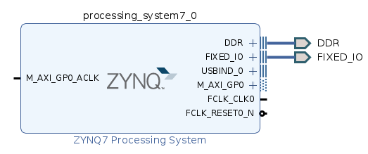
- Double click the ZYNQ7 Processing System to open the Re-customize IP dialog box.
- Click the MIO Configuration tab.
- In Application Processor Unit, uncheck the Timer 0.
- Click OK. You should get the ZYNQ7 configured like below:
Customize System for Clock and Reset
- Add the clocking wizard
- Right click Diagram view and select Add IP.
- Search and add the Clocking Wizard.
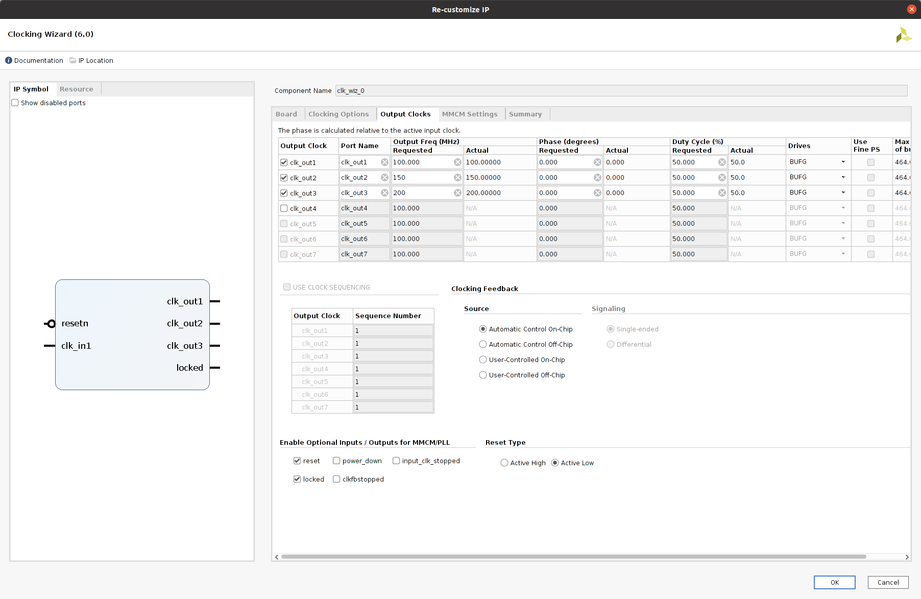
- Double click the Clocking Wizard to open the Re-customize IP dialog box.
- Click the Output Clock tab.
- Enable clk_out1 through clk_out3 in the Output Clock column. Set the Requested output Freq as follow:
- clk_out1 to 100 MHz.
- clk_out2 to 150 MHz.
- clk_out3 to 200 MHz.
- At the bottom of the dialog box set the Reset Type to Active Low.
- Click OK.
- Add three Processor System Reset blocks corresponding to the three clocks.
- Right click Diagram view and select Add IP.
- Search and add the Processor System Reset.
- Rename the reset block to proc_sys_reset_1 so that it’s easy to understand the relationship between reset modules and the clock signals.
- Select the proc_sys_reset_1 block, type Ctrl-C and Ctrl-V to replicate two modules. They are named as proc_sys_reset_2 and proc_sys_reset_3 by default.
- Connect Clocks and Resets:
- Click Run Connection Automation, which will open a dialog that will help connect the proc_sys_reset blocks to the clocking wizard clock outputs.
- Enable All automation, then make the following changes:
- For clk_wiz_0, disable clk_in1
- For proc_sys_reset_1, select slowest_sync_clk, and select Clock Source /clk_wiz_0/clk_out1 (100 MHz).
- For proc_sys_reset_2, select slowest_sync_clk, and select Clock Source /clk_wiz_0/clk_out2 (150 MHz).
- For proc_sys_reset_3, select slowest_sync_clk, and select Clock Source /clk_wiz_0/clk_out3 (200 MHz).
- Click OK.
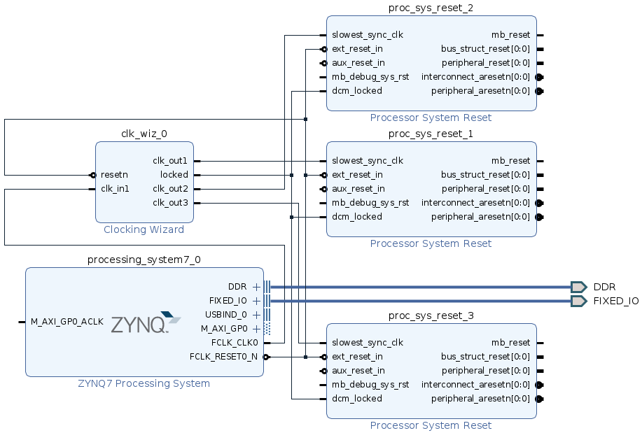
- Connect FCLK_CLK0 on ZYNQ7 Processing System to clk_in1 on Clocking Wizard.
- Connect locked on Clocking Wizard to dcm_locked on all Processor System Reset.
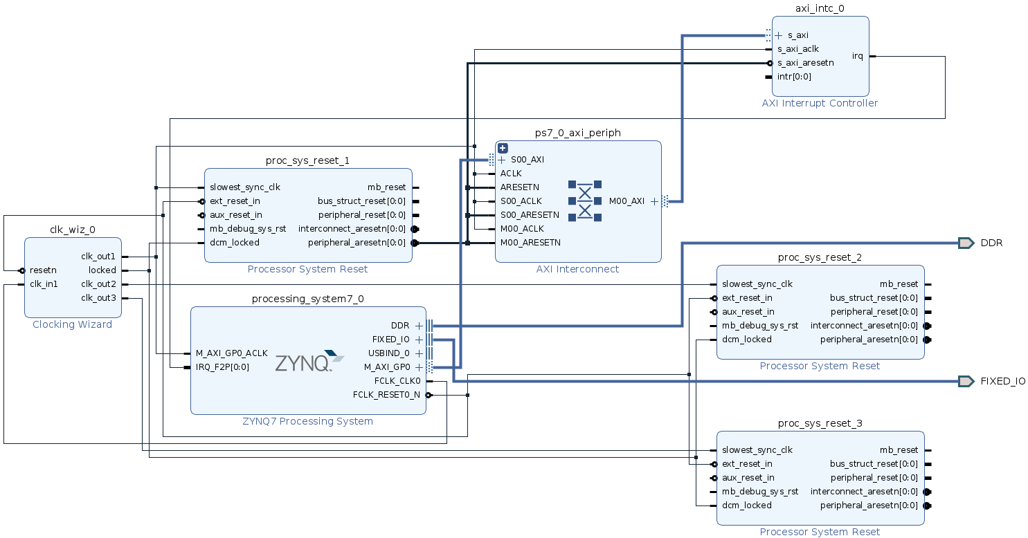
- You should get your diagram configured like below:
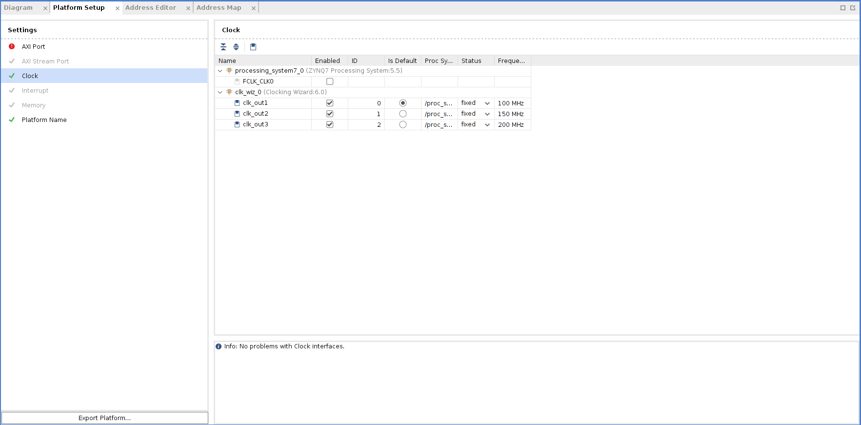
- Enable clocks for the platform
- Go to Platform Setup tab.
- If it’s not opened yet, use menu Window -> Platform Setup to open it.
- Click Clock tab
- Enable all clocks under clk_wiz_0: clk_out1, clk_out2, clk_out3
- Change their ID to 0, 1 and 2
- Set a default clock: click Is Default for clk_out1
- After everything is setup, it should report Info: No problem with Clock interface.
Add Interrupt Support
- Enable PL-PS Interrupt.
- Double click the ZYNQ7 Processing System to open the Re-customize IP dialog box.
- Click the Interrupts tab.
- Check the Fabric Interrupts.
- in PL-PS Interrupts Ports, check IRQ_F2P[15:0].
- Click OK.
- Add the AXI Interrupt Controller and configure it.
- Right click Diagram view and select Add IP.
- Search and add the AXI Interrupt Controller.
- Double click the AXI Interrupt Controller block, change Interrupt Output Connection to Single so that it can be connected to PS IRQ interface.
- Click OK.
- Connect AXI Interfaces of axi_intc_0 to M_AXI_GP0 of PS
- Click Run Connection Automation
- Review the settings (axi_intc_0 is enabled, s_axi is to be connect to /processing_system7_0/M_AXI_GP0)
- Set Clock Source for all interfaces to /clk_wiz_0/clk_out1 (100 MHz)
- Click OK
- Connect irq of the Interrupt Controller
- Connect IRQ_F2P[0:0] of ZYNQ7 Processing System to irq of AXI Interrupt Controller.
- Enable interrupt signals for the platform.
- Go to Platform Setup tab
- Go to Interrupt tab
- Enable intr under axi_intc_0
- You should get your diagram configured like below:
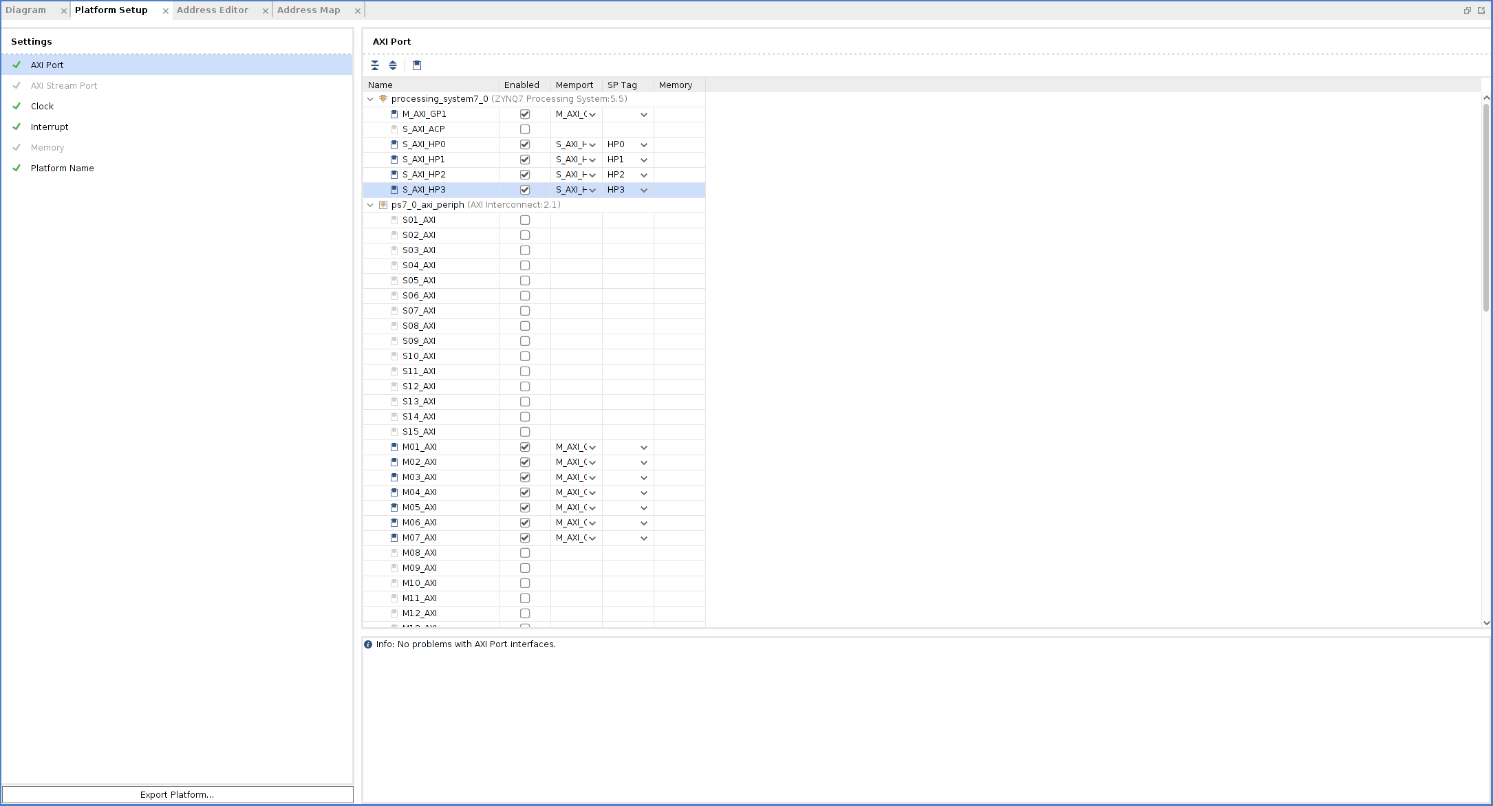
Enable AXI Interfaces for the Platform
- Enable AXI Master interfaces from PS
- Go to Platform Setup tab
- Go to AXI Port tab in Platform Setup
- Under processing_system7_0, enable M_AXI_GP1. Keep the Memport and sptag default to M_AXI_GP and empty.
- Enable AXI Master interfaces from AXI Interconnect
- Under ps7_0_axi_periph, click M01_AXI, press Shift and click M07_AXI to multi-select master interfaces from M01_AXI to M07_AXI.
- Right click the selection and click on Enable.
- Keep the Memport and sptag default to M_AXI_GP and empty.
- Enable AXI Slave interfaces from PS to allow kernels access DDR memory
- Under processing_system7_0, multi-select AXI slave interfaces: S_AXI_HP0, S_AXI_HP1, S_AXI_HP2, S_AXI_HP3.
- Right click the selections and select enable.
- Type in simple sptag names for these interfaces so that they can be selected by v++ configuration during linking phase. HP0, HP1, HP2, HP3.
Emulation Setup (Optional)
This step is only needed when creating an emulation-capable platform.
When a component comes with multiple types of simulation models, selecting SystemC TLM (Transaction-level Modeling) model would run much faster than RTL model. For Processing System component, it’s mandatory to use TLM for Hardware Emulation.
- Change PS simulation model to tlm
- Select the PS instance processing_system7_0 in the block diagram
- check the Block Properties window.
- In Properties tab, it shows ALLOWED_SIM_MODELS=tlm,rtl. It means this component supports two types of simulation models.
- Scroll down to SELECTED_SIM_MODEL property. Change it from rtl to tlm to select to use TLM model.
Export Hardware XSA
- Validate the block design
- Click the Validate Design button in the block design Diagram window
- Note: During validation, Vivado reports a critical warning that /axi_intc_0/intr is not connected. This warning can be safely ignored because v++ linker will link kernel interrupt signals to this floating intr signal.
- Create a top module wrapper for the block design
- In Source tab, right click system.bd in Design Sources group
- Select Create HDL Wrapper…
- Select Let Vivado manage wrapper and auto-update.
- Click OK to generate wrapper for block design.
- Generate pre-synth design
- Select Generate Block Design from Flow Navigator
- Select Synthesis Options **to **Global. It will skip IP synthesis during generation.
- Click Generate.
- Export the platform
- Click menu File -> Export -> Export Platform to launch the Export Hardware Platform wizard. This wizard can also be launched by Export Platform button in Flow Navigator or Platform Setup window.
- Click Next in the first information page.
- Select Platform Type: Hardware and Hardware Emulation, click Next. If you skipped the emulation setup previously, select Hardware here.
- Select Platform State: Pre-synthesis, click Next
- Input Platform Properties and click Next. For example:
- Name: zed_custom_platform
- Vendor: xilinx
- Board: zed
- Version: 0.0
- Fill in XSA file name: zed_custom_platform and keep the export directory as default.
- Click Finish.
- zed_custom_platform.xsa will be generated.